Last week was all about the order and tracking. Today will cover the unboxing, how the kit goes together, and some potential “gotchas” to watch for while putting your own kit together, if you’re following along.
The large shipping box contained two boxes. The larger box had the shell/kit, and the smaller box held the Raspberry Pi 3.
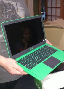
I opened the larger box first, and verified that the contents were okay. Inside were the shell, a box containing the charging cable + plug adapters, some booklets on the pi-top itself as well as the inventor’s kit, and of course, a box containing the components to the inventor’s kit that came with the purchase. I don’t plan to do anything with the inventor’s kit for a while, so I left that alone.
The first step in putting the kit together was to slide the keyboard panel down, then remove the screw holding the heat sink/GPIO bridge in place.
After that piece was removed, four screws were removed to take out the plastic card “stand in” for the Raspberry Pi 3. This card has a little cushion on one side that helped protect the heat sink/GPIO bridge during shipping. Once those were removed, I slid the hub to the right along its rail.
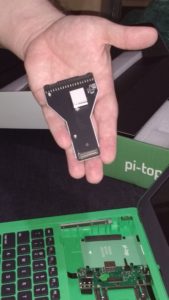
The next step was to unbox the Raspberry Pi 3 so that it could be installed. What I did not do at first, but I recommend be done if you intend to use it at all, is to install the microSD card that came with a pre-installed pi-top polarisOS image. Not installing the card before installing the Pi isn’t a deal breaker, but if you’re not going to swap cards, it’s less of a pain to do it now, rather than later. If you do intend to swap cards, or you forget to install it before installing the Pi into the case, the little tool they include includes a groove for pulling/guiding the card into and out of the Pi.
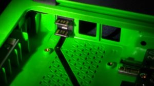
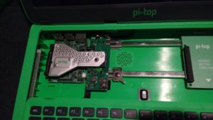
To install the Pi, I had to line up the two USB prongs inside the case with the left most set of USB sockets on the Pi, then gently push up (toward the back of the case) to seat the board. The next step was to put the screws back in to hold the Pi in place. The holes in the Pi didn’t quite line up right with the holes for the screws, so a little effort may be needed in getting the Pi seated properly while installing these screws.
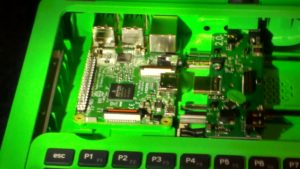
Once the screws were in place, I had to carefully slide the hub such that the audio plug and the HDMI plug slid into their respective sockets on the Pi.
Finally, I lined the heat sink/GPIO bridge up with the GPIO pins on the Pi, and carefully seated it until the pins on the other side seated into the smaller groove on the hub. Once it was snugly in place, I installed the last (longest) screw to keep it seated.
With all of the components in play, and the microSD card installed, the last step was to slide the keyboard back into place and turn the machine on. My first boot was to the pi-top polarisOS they included with the device, so that I could check that everything worked okay with their included software.
I noted that the battery indicator within polarisOS showed a 33% battery status, so I shut it back down and plugged it in. It took a few hours to charge to full. While charging the indicator light next to the USB ports on the back flashes. When it is finished, it turns solid green.
Next week will cover the first boot, general poking around, and discovery of tools within polarisOS.